Oil quenching
Written in the framework of the "Fluids and quenching systems" committee
N.B.: The information contained in this sheet comes from reliable sources. Nevertheless, it is provided without any guarantee, express or implied, of its accuracy.
3.1 Description and Classification
In general, mineral and/or synthetic bases are used for the design of quenching oils, whereas the ester-containing oils used in the past have practically disappeared due to their sensitivity to oxidation (resulting in increased viscosity, degradation of quenching power, sticky deposits on parts and plant components, etc.).
Petroleum cuts from refined crude oil are classified into different groups according to the API classification (see fig1). Each group has different technical characteristics which are listed in table 1 below.

Table 1: API Grade Classification Table
For many years, quenching oils were formulated from Gr I base oils. The evolution of the refining market and the new specifications of motor oils, have favored the development of Gr II and Gr III oils. The medium/long term scarcity of Group I has favored the development of quenching oils formulated from Group III.


Fig 1: Oil refining process.
These obtained cuts, depending on the desired characteristics, are improved by additivation. These additives are generally classified into five main families.
- Antioxidants: protection of oils against oxidation in service.
- Accelerators: increase the drasticity of the oil by modifying the transition temperatures of the boiling phase.
- Dispersing detergents: keeping impurities in suspension, reducing the formation of sludge at the bottom of tanks, increasing the boiling range.
- Emulgators: improving the cooling power of the oil, sensitivity to water, improving the cleaning of treated parts. Emulgators: improve the cooling power of the oil, sensitivity to water, improve the cleaning of treated parts.
- Compounds or fats: increase the wettability of the oil, sensitivity to water and oxidation, which has an impact on the oil's performance in service. This type of additive is in the process of disappearing
It is understood that formulations may contain a combination of several of these additives as long as they are compatible with each other...
3.2 Cooling mechanism
To meet the needs of heat treatments, there are types of adapted formulations grouped into several categories:
*Mineral oils for cold, semi-hot or hot tempering
Cold soak: these are generally oils more or less doped with antioxidants that do not affect the cooling power, low viscosity (Iso VG 15 to 32) and used between 40 and 80 ° C maximum.
Semi-hot quenching: these are oils reinforced with antioxidants, of medium viscosity (Iso VG 46 to 68) whose quenching power has been improved and which can withstand operating temperatures of up to 120°C.
Hot soak: these are additivated and reinforced mineral oils (with antioxidants and dispersants), with higher viscosities (Iso VG 100 and higher), high flash point and low volatility, with improved soaking power.
Very hot quenching: these are mixed mineral-synthetic or synthetic oils, with higher viscosities (Iso VG 100 and higher), additivated and reinforced like hot quenching oils.
*Accelerated Oils:
These are mineral oils doped with additives that modify their vaporization process, the transformation points of the boiling phase. Depending on their composition and the choice of bases, they are used for cold, semi-hot and hot quenching.
*Washable linens:
They are mostly mineral oils reinforced with emulgators, easily removed by washing with water. They are intended for cold, semi-hot and hot dips. The emulgators modify the cooling power of the oil. These oils emulsify in the wash water. They are not recommended when washing in a washing machine with a detergent bath.
*Soluble oils:
These are mineral oils strongly doped with emulsifiers, or synthetic bases, allowing their use at a more or less high percentage in solution in water, used mainly in tempering stop.
*Vacuum Quenching Oils:
These are mineral or synthetic oils with a very low vapour pressure.
An ISO standard classification is currently being prepared. It is based on the NFT 60-512 standard, developed by the ATTT. It includes 5 main categories (table l).

Table 2: Table of hardening oil categories
Cooling and soaking power
A distinction must be made between these two terms. As we have just seen, the cooling power of a quenching fluid is the ability of this fluid to evacuate calories from a hot metal. It is characterized by the measure of drasticity.
Hardening power is the ability to give a metal alloy mechanical characteristics and to obtain homogeneous microstructures with minimum deformation.
In the case of steel parts, we characterize a posteriori :
- surface and core hardness level
- profile of the hardened depth
- microstructure obtained and homogeneous and in some cases
- dimensional deformations undergone.
The numerous studies carried out do not make it possible to reliably establish a law linking the kinetic data of an oil, established by the drasticity measurement, and the hardness results after quenching.
However, there seems to be a clear trend:
- At q1 (temperature at the beginning of the boiling phase), the oil with the lowest q2 (temperature at the end of the boiling phase) will have the highest hardening power, with the risk of causing greater deformations.
- At the same q2, but relatively low, the oil with the highest q1 will have the strongest hardening power.
- The more the boiling range is extended, the higher the core hardnesses will be, the more one will risk problems of deformations.
The effects of quenching on the hardness levels are represented by the U-shaped curves in Figures 2 and 3, for 100Cr6 (diameter 25 - 3 oils) and 25CrMo4 (diameter 25 - 2 oils) steels.
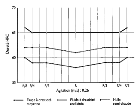
Fig 2: Influence of the drasticity on the U-curve.
Steel: 100C6; Diameter: 25mm; Length: 75 mm
(From CASTROL document)

Fig 3: Influence of the drasticity on the U-curve.
Steel: 25CrMO4; Diameter: 25mm; Length: 75 mm
(From CASTROL document)
The overall hardening severity of a plant is taken into account in the NFT 60-179 standard. This method is based on the measurement of hardness at different points of a wedge specimen hardened under industrial conditions.
It takes into account all the parameters influencing the process from the time of loading to the time of leaving the quenching tank. The use of a 2-step test tube is also recommended for these severity tests because of its ease of use.
3.3 Usage constraints (HSE - Product disposal)
Fire hazard and quenching oils
Fire is the most important risk when using quenching oils. Every year in France, dozens of oil quenching tanks catch fire, mostly due to non-compliance with the rules of use of the oils, which are flammable products, or to insufficient maintenance of the equipment.
The most common cause of fire is water pollution of the oil. When the water vaporizes on contact with hot parts, it causes fine oil droplets to form which quickly ignite.
Similarly, water can cause the oil pan to foam up and spill over dangerously in the case of built-in pans.
Table 2 shows the main cases of fire origin and the corresponding preventive and corrective actions.
Means of extinguishing oil baths:
- dry ice
- foam
- powder
The small bins will be equipped with a cover to smother the fire. In case of fire, the workers will wear a self-contained breathing mask because of the abundant fumes.
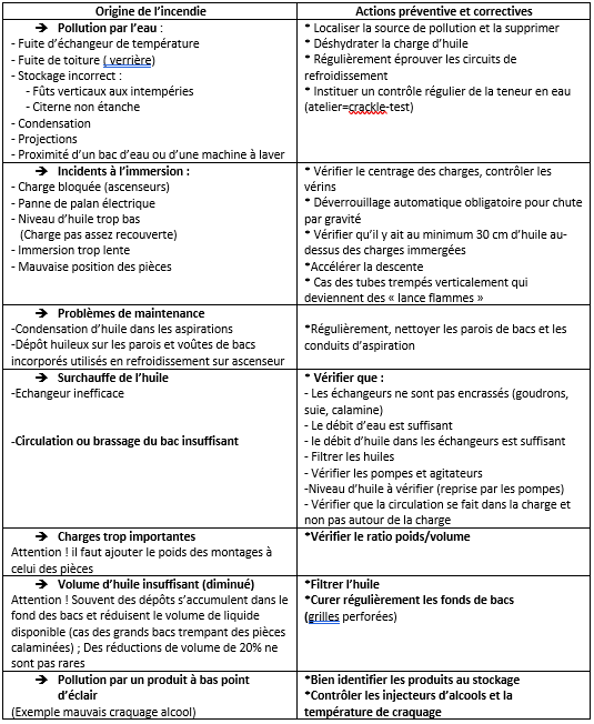
Table 3: Summary table of major fire incidents and corrective actions
Staff protection
The safety data sheet. For each product delivered, the supplier, whether manufacturer or reseller, is obliged to provide the user with a safety data sheet in accordance with standard NFT 01-102.
This safety data sheet contains information on product components, hazards, handling and storage instructions as well as information on transport and disposal conditions.
In the appendices, you will find safety data sheets for 3 quenching fluids: oils, polymers, salts.
Confidential data. The supplier is obliged to provide only the occupational physicians or the health insurance funds with the detailed composition of the delivered products if they request it. Generally, the request is made in writing by the doctor, and the answer is sent by confidential mail recommended.
Some recommendations:
* Use of oils. The vapors will be sucked up and the operators will be protected by gloves and aprons (risks of "oil buttons").
Treatment and disposal of quenching fluids and their waste
The practice of heat treatment requires the use of products that must be disposed of after use, either as is or mixed with bodies foreign to their original formulation (soot, lyes, water, metal particles, etc. ...).
Due to the service demands, quenching fluids can also generate waste or decomposition products which must be treated within a legal framework in order to protect the environment.
The following tables list the main wastes generated by quenching fluids and the nature of the environmental hazards they represent.

Table 4: Major releases of quenching fluids

Table 5: Coolant Wastes
The increase in thermal treatment waste is not inevitable.
Waste reduction
Waste reduction must be a joint effort between Users and Suppliers - everyone has a role to play in minimizing waste within a legal framework.
As reduction at the source is essential to limit discharges, the following table lists some basic rules which, if applied by suppliers and users, will make it possible to limit liquid and gaseous waste from quenching fluids very significantly at their source.

Table 6: Source reduction of liquid waste; Role of suppliers and users
3.4 Maintenance and aging of the fluid
Maintenance and filtration of quenching oils
1) General instructions
Periodic checks must be performed on the following items:
characteristics of the oil in use (see § 3.6).
oil level in the tank and its reserve.
Control of immersion heaters
control of the temperature indicators.
condition of pumps, filters and cooling circuits (pressurization)
2) Filtration of quenching oils
During use, the quenching oil is normally polluted due to its inevitable decomposition on thermal shock and the addition of various impurities to the bath
*Metal particles
These are chips from poorly cleaned parts prior to heat treatment or oxides or scale which, on thermal shock, detach from the parts or fixtures. The larger particles settle to the bottom of the bath, and the finer ones remain in suspension in the oil when the bath is agitated.
The metal oxides present in the oil catalyze its oxidation and accelerate its degradation.
After the oil has rested, the settled metal particles must be reduced or the charge must be filtered out at regular intervals.
A preferable solution is to install a perforated steel mesh filter (approx. 700 to 900 microns) on the suction side of the circulation pump.
*Non-metallic particles
These are tars from the decomposition of oil and soot from the furnace atmosphere as well as the residues of protective pastes. These non-metallic contaminants are deposited in the bottom of the pans, on the hardened parts and in the heat exchanger tubes.
The disadvantages are:
->Dirty parts that are difficult to clean => risk of corrosion of parts during interoperation
-' Heterogeneities of hardness
-' Fouling of the exchangers with overheating of the oil by loss of efficiency.
Filtration should be done with cartridge filters of 5 to 10 microns.
Ideally, the tanks should be equipped with a double filter under pressure, which will successively eliminate the metal particles, then the soot and tar.
Continuous filtration of the oil baths significantly increases their service life.
Presence of water in the quenching oil
The presence of water in a quenching oil with a content higher than 300 ppm has an impact on the cooling performances. Indeed, water has a quenching gas pedal action that can present a risk of tapping and/or deformation on the parts depending on the steel alloy.
The water will increase the maximum cooling rate as well as the cooling rate to 300°C.

_____ Huile de trempe froide < 200 ppm d’eau
_____ Huile de trempe froide > 500 ppm d’eau
Fig 4 : Impact de l’eau sur la courbe de refroidissement ( Sonde INCONEL ISO9950)
The sources of water pollution can be numerous, the most common are listed in the table below:

Table 7: Table of commonly encountered water pollution sources
If the fluid is contaminated with water :
Either a steaming of the oil allows to decrease this water content by evaporation (low water pollution)
Either a decantation of the fluid allows to eliminate the water by the bottom of the tank (high water content).
Depending on the additive chemistry of the quenching oil, water removal can be more or less difficult. Some additives have an affinity with water, which favors its emulsion by the quenching fluid.
3.5 Recommendations for starting the installation
The conditions of use of a quenching oil are essential to maintain its physical and chemical characteristics, to obtain optimal and repeatable results on the quenched parts and to limit the risks in terms of hygiene and safety.
The main parameters to be considered are:
- The quenching tank
- Fluid mixing
- Oil temperature in operation
- Pollution risks
- Filtration.
Tempering tanks
Generally, modern quenching tanks are manufactured by specialists or furnace manufacturers, who take into account the determining parameters to ensure a good cooling of the quenched parts in good safety conditions and maintenance of the properties of the oil (temperature of the fluid and the parts, quenched mass, frequency of quenching, agitation, cooling of the oil etc.)
However, it is not uncommon for the stresses on the quenching bath to increase over time or for a "homemade" tank to be used.
Some parameters must be taken into account very seriously to avoid fires or rejects on treated parts.
Practical information
MATERIAL: ordinary steel
LOCATION: away from water and near the oven
VOLUMES of OIL required on tanks equipped with cooling circuits :
a) Discontinuous quenching (charges spaced in time)
- Bath temperature increase = 30°C (40 -> 70°C): 11 liters per kg soaked per hour.
- Volume reduction coefficient for solid parts

a) Continuous quenching (continuous furnaces): 8 liters per kg quenched per hour
Agitation of quenching oils
Stirring of quenching oils includes two often confused phenomena: "circulation" and "agitation".
* The circulation of the quenching oil consists in renewing the liquid inside the tank with preferential hydraulic flows. In the circulation, the major action is the suction favoring the formation of vortex with a non-directional discharge characterized by low flow speeds.
* Agitation is the creation of a powerful directional hydraulic flow capable of successively propagating, at any point of the oil, disordered turbulences in order to obtain no low speed zone, whatever the geometry of the tank and the obstacles it contains (parts, assemblies).
Role of agitation
- Renew the liquid on the surface of the parts for a good heat exchange.
- Achieve uniform cooling (Figure 5) avoiding soft spots and deformations.
- Homogenize the temperature in the quenching tank.
Effect of agitation
- Modification of the drasticity curve by increasing the cooling rate in the calefaction and convection phases (Figure 6).
- Improvement of the soaking power of oils, and consequently, of hardnesses (level and homogeneity).
- A tangential and laminar flow follows the profile of the parts and limits the deformations.

Fig 5 : Influence of the agitation on the U curve
Steel : 100C6 ; Diameter : 25mm ; Length : 75 mm
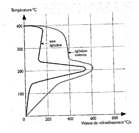
Fig 6 : Effect of agitation on the drasticity of the oil
- A transverse flux violently strikes the surface to be cooled and causes significant thermal shocks. This flux will be used for the cooling of steel with low hardenability and for parts where the risks of deformation and tapping are low.
The agitation speed or flow rate will be adapted according to the desired hardening severity, the geometry of the treated parts and the design of the loads to be hardened.
- For a quenching oil, the speeds will be between 0.2 and 0.5 m/s.
- The measurement of a stirring speed can be done with a propeller anemometer in the quenching zone at different points of the immersed load.
Recommendations
* The liquid flow must be directed on the load (and not around it). Deflectors should be used to force the liquid to flow through the load or to circulate over the entire surface to be cooled. In the case of multiple part loads, the parts should be arranged in such a way as to favour their contact with the fluid and avoid flow losses.
* As a stirring device, pumps or propeller agitators should be used, but NEVER AIR in order to limit the oxidation of the oil.
* The use of submersible mixers is particularly interesting. Submersible mixers do not require any boiler structure, their installation is simple and fast, and the liquid flow is easily modulated in orientation and power.
*Too little agitation can lead to poor gas removal during the boiling phase, which can lead to the formation of an oxide on the surface of the part.
Temperature of use of quenching oils
The temperature of a quenching oil will have a more or less pronounced influence on its viscosity and drastic properties.
- Influence on viscosity: viscosity decreases as the temperature rises, which favors the circulation of oil, and especially during convection and limits consumption by entrainment with the parts (Figure 7).
- Influence on the drasticity: the rise in temperature of the oil, generally raises the transition temperatures q1 and q2 (Figure 8).
In general, for a non-additive hardening oil, the increase in its operating temperature slightly reduces its hardening power. The use of hot quenching oil at 160/180°C is favorable to limit deformation.

Fig 7 : Effect of viscosity as a function of temperature
(From Castrol document)
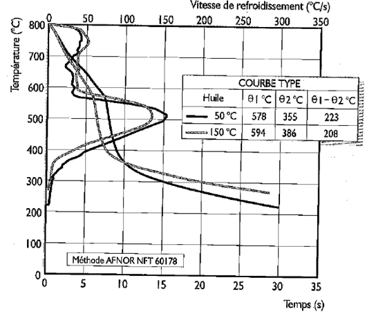
Fig 8 : Influence of temperature on drasticity
(From Castrol document)
Recommendations
- Do not use oil at room temperature (too high viscosity).
- Never use a quenching oil at a temperature above the flash point minus 60°C.
- The power of the heating elements shall be limited to 1.5 W/cm2.
- Above 100°C, the oil will be under gas protection.
3.6 System Maintenance/Equipment
Tempe oil is highly solicited since parts are quenched at temperatures between 700 and 1250°C. It is subject to 3 types of stress: thermal shock, contamination from various sources and oxidation.
These severe stresses can lead to ageing of the quenching oil, which changes its characteristics. It should be noted that aging affects both the base oil and the additives.
The tests used to characterize quenching oils are those that apply generally to petroleum products. Most of them give physico-chemical characteristics and are standardized.
We will limit ourselves to recall the main characteristics to be taken into account and the associated test methods.
*Color (NF EN ISO 2049): determination by comparison with standard glass plates coloured in the mass (numerical scale from 0 to 8).
*Density (NF EN ISO 3675): determination by aerometer measured at 15 °C. The density of an oil is the quotient of its mass by its volume. Identification of base oils, pollution problems.
*Viscosity (NF EN ISO 3104): determination of the time required for a given quantity of oil to flow through the calibrated orifice of a viscometer tube by simple gravity, at a defined temperature. Kinematic viscosity: measurement expressed in mm²/s at 40 or 100 °C. Measures the evolution of the oil in service (oxidation, cracking), pollution problems.
* Viscosity index (NF EN ISO 2909): measures the effect of a temperature variation on the viscosity of an oil.
*Flash point: determination of the minimum temperature in °C to which an oil must be brought for the first vapors emitted to ignite (blue flash) spontaneously in the presence of a flame under standardized conditions. Measurement of fire risks, evolution of the oil in service (oxidation), pollution problems.
Standard NF EN ISO 2592 : measurement of the flash point in open vessel.
Standard NF EN ISO 2719 : measurement of the flash point in a closed vessel Penski Martens.
*Fire point (NF EN ISO 2592): determination of the minimum temperature in °C to which an oil must be brought for it to burn for five seconds without interruption. Always higher than the flash point.
* Ash content (NF EN 6245): percentage by mass of residue resulting from the calcination under standardized conditions of a certain quantity of oil, the method used depends on the presence or absence of additives forming ash. Measures the presence of metal oxides and loss of additives.
*Conradson residue (NF EN 6615): percentage by mass of deposits related to the calcination in closed vessel under particular conditions of a certain quantity of oil. Measures the presence of carbonaceous bodies, indication of the carbon potential in the furnace.
*Water content by KF method: percentage of water contained in the oil. Measures water pollution (cooling system leaks, condensation); there are two methods:
NF ISO 6296 : Volumetric potentiometric method
NF EN ISO 12937 : Coulometric method capable of detecting very low water content.
*Infrared spectrometry: Oil identity card. Measurement of oxidation and cracking peaks on the product in service, of the presence of additives, of possible pollution.
*Drasticity (ISO 9950/ASTM D 6200) ability of a fluid to evacuate, more or less quickly, the calories stored in a part previously heated and immersed in this fluid. Measures the state of aging of an oil.
*Drasticity/ Establishment of cooling curves
As far as the characterization of the cooling power is concerned, this characteristic is of primary interest to the user. This cooling power measurement or drasticity measurement is based on the monitoring of the temperature of a specimen in INCONEL 600 (ISO) during the quenching process.
The principle is as follows:
Immersion in the oil to be tested of a cylindrical test tube heated at high temperature. The thermoelectric couple, crimped in the center of this test piece, allows to follow the evolution of the temperature of this last one during all the cooling time.

Due to the low inertia of the specimen (high conductivity and low mass), it is assumed that the curves thus obtained are characteristic of surface heat transfer and therefore of the cooling capacity of the oil tested.
The drasticity curves allow to visualize the transition points that delimit the three phases of the cooling process. Their interpretation allows to :
- compare different oils
- measure the influence of the different constituents of the oil, of the quenching parameters (agitation, temperature...), of the various pollutions, if it is practiced in the quenching tank.
- to follow the evolution of the oil performance in service.
ISO 9950 standard
A standardized Inconel 600 cylinder equipped with a thermocouple in its center is heated to 850°C and then soaked in 2 liters of oil at rest.
The recommended oil temperature is 40°C, but this can be adjusted according to the application.
Using the two recorded curves, we define:
- Vr max I maximum cooling rate in °C/ s
- Tvr max. temperature at maximum cooling rate in °C
- Vr at 300 °C
- t at 600°C: time elapsed to cool the specimen from 850 to 600°C in s
- t at 400 °C : time elapsed to cool the test tube from 850 to 400 °C in s
- t at 200 °C I time taken to cool the specimen from 850 to 200 °C in S
All the conditions of the procedure and the calibration are fixed by the standard.
There are other standards such as, the Japanese standard JIS K 2242 which uses a small diameter silver sensor where the thermocouple is attached to the surface of the sensor or the American standard ASTM D 3520 which subjects a steel ball in a quenching oil to a magnetic field. The speed of the ball to reach the edge of the container is measured.
Note that the NFT 60-178 method known as the Silver Sensor method is practically no longer used because the supplier of the sensor that meets the manufacturing specifications of the standard has ceased manufacturing these sensors.
*Cracking- thermal shocks
The sudden contact of the oil with the metal at high temperature causes the oil to crack. The long carbon chains of the base undergo a shearing. We have then production of light fractions.

Table 8: Summary table of the consequences and remedies of cracking
*Oxidation
It is caused by the presence of oxygen in the quenching medium. The oxygen can come from the environment surrounding the quenching tank. The chemical reaction corresponding to this phenomenon is well known. The first phase of the process consists of the formation of a free radical which is transformed by the intermediary of an oxygen radical into a peroxide which itself being unstable generates two new free radicals leading to a chain reaction. With the appearance of new free radicals, we have production of carboxylic acids.
This explains the exponential progression of this phenomenon, which is very difficult to curb (Figure 9).

Fig 9 : Highlighting of the oxidation peak at 1710cm-1 (from doc.Renault).
Comparison of the spectra of an oil in its new state and after an accelerated oxidation of 96h.
(Oxygen bubbling oxidation test)
A method of evaluation of the artificial ageing of quenching oils had been worked on by the A3TS quenching fluid commission but its work could not lead to the filing of a standard with the AFNOR.

Table 9: Summary table of the consequences and remedies of oxidation
*Contaminants
They are of several kinds as summarized in the following table

Table 10: Summary table of contamination sources.
Follow-up in service
As mentioned above, the properties of quenching oils can change considerably depending on the conditions of use. The operating temperature, bath mixing and bath pollution are all parameters to be considered. Regular monitoring is therefore essential to detect any disturbance that could compromise the quality of the parts treated, the life of the baths and the safety of people and installations.
The characteristics regularly monitored are as follows:
*Viscosity
The measurement of the viscosity of the product in service gives us a first indication on the type of predominant degrading phenomenon (oxidation/cracking) (figure 10) :

Table 11: Summary table of viscosity evolution sources

Fig 10 : Example of oxidation on a quenching oil in a batch furnace (From Renault document)
* The acid index
The acid number is used to measure the acidity of the oil. After numerous ring tests in the Chemistry section of the ATTT Quenching Fluids Commission, it was found that this measurement is not reproducible. Infrared measurement of oxidation is recommended.
Water content
Values above 500 ppm or 0.05% in use are not recommended. The non-reproducibility of this measure recommends that you contact your oil supplier.
* Flash point open vessel/flash point closed vessel
These measurements allow the evaluation of the flammability limits of the quenching fluid in contact with a flame.
For open tank installations, it is recommended to perform an open vessel flash point (NF EN ISO 2592/Grading Code T60 : 118).
For installations in a built-in tank, it is recommended to perform a flash point in a closed vessel according to the Pensky Martens method (NF EN ISO 2719 / Classification number M 07.019).
Note: Closed cup flash point values are lower than open cup flash point values.
For safety reasons, it is recommended that the flash point of the quenching oil measured during operation is at least 50°C higher than the operating temperature of the oil in the system.

Table 12: Summary table of flash point evolution sources
*Impurities
There is no standard method for measuring this parameter. Filtration on cellulose membrane with 5 μm porosity is often used. The solvent used in most cases is petroleum ether. The analysis is both quantitative and qualitative:

Table 13: Summary table of pollutant determination after 5µm filtration
It is also possible to make other analyses from the filter (calcination, infrared by ATR, ...).
*Infrared measurements
The Infrared spectrum of the product allows to quickly visualize the state of the oil. This method is both qualitative and quantitative. In the various circular tests carried out by the ATTT Quenching Fluids Commission, this is the most reproducible method.
Appearance of a peak = 1710 cm-1 : presence of carboxylic acids coming from the oxidation phenomenon. The more intense the peak, the more important the phenomenon. Some gas pedal additives have a peak at this wavelength. In this case, we must make the comparison with new oil
Appearance of a peak = 910 cm-1 : presence of an oil cracking phenomenon. The more the peak is important, the more the phenomenon is important.
The presence of water can also be detected by the appearance of a rounded shape around 3600 cm-1.
The A3TS Quenching Fluid Commission, in collaboration with CETIM, is working on a project to standardize the infrared method for monitoring quenching oils
*Drasticity
It allows to evaluate the cooling power of the oil.