Cryogenic quenching
Written in the framework of the "Fluids and quenching systems" committee
N.B.: The information contained in this sheet comes from reliable sources. Nevertheless, it is provided without any guarantee, express or implied, of its accuracy.
1. PURPOSE
Creation of a dedicated chapter for the book "Quenching fluids. Note: paragraphs 1 to 3 are almost entirely taken from the A3TS web page dedicated to cryogenic treatment(http://www.a3ts.org/actualite/commissions-techniques/fiches-techniques-traitement-surface/traitement-par-le-froid-ou-traitement-cryogenique-ou-sub-zero/)
2. Principle
Cold treatment (or cryogenic treatment) consists of cooling mechanical parts below room temperature after a quenching heat treatment. The holding temperature is between 0°C and -150°C (most often between -80 and -100°C for steels).
2.1. Justification of the cold treatment on steels
The need to reach a temperature lower than the ambient temperature supposes that metallurgical transformations can occur for temperatures reached lower than this one. This is the case for some iron-carbon alloys for which the Mf point of the end of the transformation of austenite into martensite is itself lower than 0°C, hence the existence ofresidual austenite (or retained austenite) after quenching.
Mf depends on the carbon content and the chemical composition of the alloying elements.
Mf (°C) = (361 to 461) - 474 (C %) - 33 (Mn %) - 14 (Cr %) - 21 (Mo %)
(Steven and Haynes law) for low alloy steels.
Mf is lower than 0°C as soon as the carbon content is higher than the eutectoid (0.8% carbon in the absence of alloying elements), hence an increased risk of residual austenite after case hardening.
The existence of residual austenite in the structure constitutes an unstable situation, which will decompose if the temperature is lowered sufficiently to reach the temperature Mf. It can also be transformed under the action of destabilizing conditions: high stresses, vibrations, cyclic stresses, operation at temperatures close to the tempering temperature.
The austenite will then decompose in an uncontrolled way into martensite (sometimes called secondary martensite) producing volume deformations and risks of local over-stressing which can go as far as cracking. This non-returned martensite is also brittle.
Beside martensite, austenite is a constituent of low hardness. Its presence is reflected by soft patches.
Cold treatment will therefore have the effect on steels containing residual austenite:
increase the hardness and the elastic limit with a correlative decrease in resilience and an increase in internal stresses,
increase the dimensional stability of the parts. It is therefore particularly recommended for gauges and elements with very tight clearances.
It is essential on mechanical components intended to be mounted by press fit, by shrink fitting with liquid nitrogen or working at low temperatures (case of cryogenic components or aeronautical structural parts).
2.2. Justification of cold treatment on aluminium alloys
After quenching, aluminum alloys suitable for heat treatment hardening are in their maximum malleable state (fresh quenching state), they will harden by tempering or aging. For parts that need to be deformed or calibrated between hardening and final hardness, the malleable state is maintained by keeping the parts in a cold box in order to delay the start of the maturation process. This stay will allow the parts to be taken as and when the deformation equipment is available before the maturation process starts.
3. APPLICATION OF COLD TREATMENT
Industrial applications on steels:
Deformation tools
Cutting tools
Parts made of extra hard alloyed cast iron
Cemented parts
Sizes and gauges
Precision cutting punches
Aeronautical parts
3.1. Precautions for implementation
Immersion in a very low temperature environment constitutes a thermal shock that can lead to the risk of tapping. This is why a stress relieving tempering at low temperature (125°C for example) can be recommended in order to reduce the brittleness of the martensite which will be exposed to the cold and to the stresses of the secondary martensite formation, even if it can stabilize the residual austenite. Immersion in an air-cooled chamber is preferred to immersion in a cold liquid such as liquid nitrogen or nitrogen-alcohol mixtures.
After the cold treatment, the austenite previously retained is completely transformed into fresh martensite which must be quickly subjected to stress relieving tempering in order to avoid the risks of delayed tapping.
3.2. Types of materials suitable for the application
Steels X100CrMo17, X200Cr12, 90MnCrW 5
High speed and semi high speed steels
Cemented steels: 16NiCr12, 16CrNiMo13, 20NiMo14, 16CrMn6, etc.
Bearing steel type 100Cr6
Examples of typical range applications:
Threaded gauge material X200Cr12
Overall draft
Finishing and threading with grinding reserve
Tempering
Tempering 180°C
Passage to cold - 80°C
Tempering 180°C
Rectification
Aeronautical part X100CrMo17
Rough machining
Stabilization
Machining and finishing
Passage to cold - 80°C
Tempering 160°C
Passage to cold - 80°C
Tempering 160°C
Passage to cold - 80°C
Tempering 160°C
Application on aluminum alloys
Example: on a 7075 alloy part after fresh quenching, inter-operation holding in a cold chamber at -23°C, ability to bring back from ambient temperature to -23°C in less than 15min, without exceeding -18°C in the chamber.
4. Implementation
4.1. Material used
Isothermal liquid nitrogen chamber
Compressor cooled cabinet (temperature limit - 100°C)
Refrigerated cabinet with liquid nitrogen circulation coil (nitrogen flow regulates the temperature)
Cryogenic cell: the cryogenic fluid (nitrogen or liquid CO2) is injected directly into the cell at a rate adapted to the characteristics of the products. A ventilation system ensures the rapid vaporization of the cryogenic fluid and a homogenization of the temperatures:
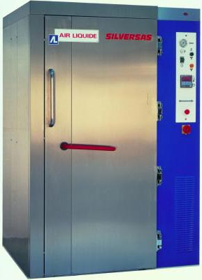
Figure 1: Silversas™ cell (credit Air Liquide®)
Heat treatment furnace for quenching and/or tempering equipped for cryogenic treatment.
Example: SCHMETZ® and BMI® furnaces equipped with the "cool plus" system developed and patented by SCHMETZ®. Liquid nitrogen (-196°C) is evaporated uniformly and directly in the vacuum heating chamber and is stirred homogeneously by means of the convection turbine. The heat is extracted through a special exhaust pipe in which a temperature measurement is performed. The temperature control acts on the injected liquid nitrogen flow rate by comparing the set temperature with the measurement in the evacuation pipe and/or in the furnace chamber.
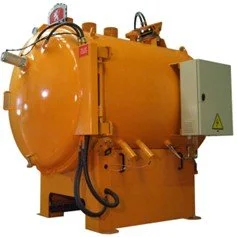
Figure 2: B54RC tempering and cryogenic treatment furnace (credit BMI®)

Figure 3: B54RC tempering and cryogenic treatment furnace
- front view, open door (credit NTN-SNR)

Figure 4: B54RC tempering and cryogenic treatment furnace
- view of the inside of the treatment chamber (credit NTN-SNR)

Figure 5: B54RC tempering and cryogenic treatment furnace
- view of the arrival and extraction of the cryogenic treatment nitrogen (credit NTN-SNR)
4.2 Constraints on use
Cells and furnaces that allow cryogenic treatment based on liquid nitrogen vaporization can be large consumers of fluid. It is therefore necessary to dimension the liquid nitrogen storage and distribution installations accordingly. The distribution network is specific and it is recommended to use double wall vacuum pipes to avoid heating.
A certain number of specifications and standards consider the end of cryogenic quenching as a "standard" thermal quenching treatment. The means implemented must therefore be monitored in the same way from a pyrometry point of view, data recording, maintenance, etc.